- Stock: In Stock
- Model: RDDLZ-STEP-D100220
- Weight: 1.00
- SKU: RDDLZ-STEP-D100220
Available Options
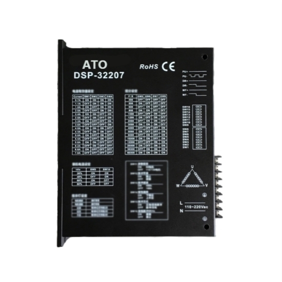
3-phase digital stepper driver, AC 100V-220V power supply, maximum output current 7A/ phase, 30000 steps/ turn of the 16 subdivision mode optional, suitable for 3 phase Nema 34, 42 stepper motor, manufacturer direct sale.
Function Description
| Pin | Feature | Operation Instructions |
| PWR | Power Indicator Light | When powered on, the green light is on. |
| OC | Over-current/ under-voltage/ over-voltage indicator light | Current is too high, voltage is too high or too low, the indicator light is on. |
| PU+ | Input signal photoelectric isolation positive terminal | Connect the signal power 5V-24V can drive. |
| PU- | SW15=OFF, it is the reverse step pulse signal SW15=ON, it is the forward step pulse signal | The falling edge is valid, and the motor takes one step each time when pulse goes from high to low. Requirements: low level 0-0.5V, high level 4-5V, pulse width> 2.5μs. |
| DR+ | Input signal photoelectric isolation positive terminal | Connect the signal power 5V-24V can drive. |
| DR- | SW15=OFF is the forward step pulse signal SW15=ON is the reverse stepping pulse signal | The falling edge is valid, and the motor takes one step each time when pulse goes from high to low. Requirements: low level 0-0.5V, high level 4-5V, pulse width> 2.5μs. |
| MF+ | Input signal photoelectric isolation positive terminal | Connect the signal power 5V-24V can drive. |
| MF- | Motor release signal | When the motor coil current is switched off, the motor is free. |
| FL+ | Over-current/ under-voltage/ over-voltage photoelectric isolation positive terminal | FL + connect to the output current limiting resistor. |
| FL- | Over-current/ under-voltage/ over-voltage photoelectric isolation negative terminal | FL- connect to the output, the maximum drive current of 50mA, the maximum voltage of 50V. |
| TM+ | Origin outputs photoelectric isolation positive terminal | TM + connect to the output current limiting resistor. |
| TM- | Origin outputs photoelectric isolation negative terminal | TM- connect to the output, the maximum drive current of 50mA, the maximum voltage of 50V. |
| AC | Power | AC 110-220V |
| Note: The default input signal is 5V pulse signal. When 24V input signal is required, please in series with1.8-2kΩ resistance. | ||
| U | Motor Wiring | |
| V | ||
| W | ||
Installation Size
Details
Tips: Drive circuit of stepper motors
Unipolar and bipolar driver architectures are most commonly used for stepper motors.
The unipolar drive circuit uses four transistors to drive two phases of the stepper motor. The motor configuration, as shown in Figure 1, consists of two sets of coils with center tap, and the entire motor has a total of six lines connected to the outside. Although the six-wire stepper motor is also known as unipolar stepper motor, it can actually use unipolar or bipolar drive circuit at the same time.
The drive circuit of a bipolar stepper motor is shown in Figure 2, which uses eight transistors to drive two phases. Bipolar drive circuit can also drive a four-wire or six-wire stepper motor. Although it can only use bipolar drive circuit, a four-wire motor can significantly reduce the cost of mass-production applications. The number of transistors used in drive circuits of bipolar stepper motors is twice that of transistors used in a unipolar drive circuit, in which four lower transistors are usually driven directly by a microcontroller while the upper transistor requires an upper driver circuit of higher cost.
Transistors used in bipolar drive circuits only need to withstand motor voltage. Therefore, they do not need to clamp the same circuit as unipolar drive circuits do.
