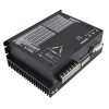
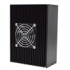
Digital Stepper Motor Driver, 3 Phase, AC 180V ~ 230V
from
$264.29
Ex Tax: $264.29
- Stock: In Stock
- Model: RDDLZ-STEP-M2207T
- Weight: 1.00
- SKU: RDDLZ-STEP-M2207T
Available Options
Create unlimited custom product blocks and display them in accordions or tabs or open blocks. Each block can be assigned to all products at once or specific products according to advanced criteria.
Create unlimited custom product blocks and display them in accordions or tabs or open blocks. Each block can be assigned to all products at once or specific products according to advanced criteria.
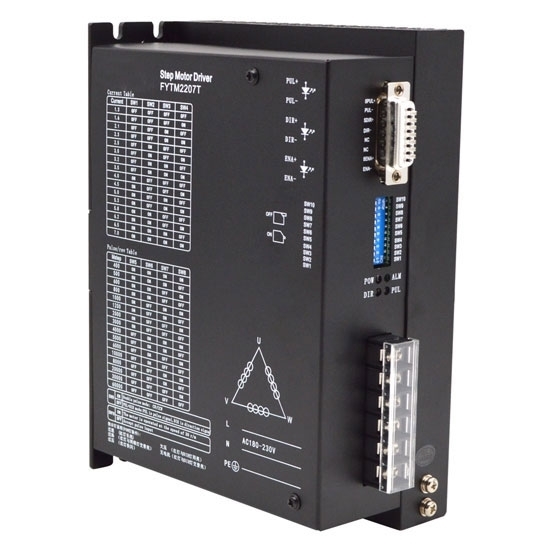
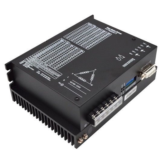
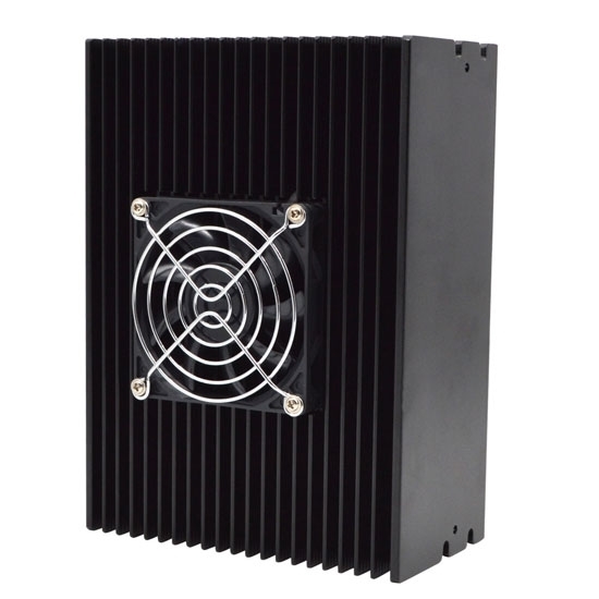
RDDLZ digital stepper motor driver is an ideal choice for Nema 42, 51 bipolar stepper motor solution. This stepper motor controller can realize precise position control even without a feedback system.
Features
- Digital stepper motor driver is high performance, extra-low noise and good stability.
- Unique control circuit, high speed response.
- When the step pulse stops over 100ms, the coil current automatically halved.
- Over current, over voltage, under voltage, short circuit protection.
- Suitable for 3 phase Nema 42, Nema 51 hybrid bipolar stepper motors.
Specification
| Model | RDDLZ-FYTM2207T | |
| Matched Motor | Nema 42, 51 3 Phase Stepper Motor | |
| Voltage | AC 180V ~ 230V | |
| Drive Current | 1.3A ~ 7.0A 16 Channels | |
| Microstepping Setting | 60000 steps/rev 16 Channels | |
| Hightest Pulse Frequency | 200Kpps | |
| Certification | CE, FCC, RoHS | |
| Dimensions | 202 x 147 x 78mm | |
| Weight | 1.5kg | |
| Function Description | ||
| Functions | Operation Instructions | |
| PUL+ | Positive End of Control Pulse Signal | Connect to +5V power supply, +5V ~ +24V can be driven, higher than +5V need to connect current limiting resistor. |
| PUL- | SW9=OFF, PUL is the pulse control signal | The falling edge is valid, and the motor takes one step whenever the pulse changes from high to low. Input resistance 220Ω. Requirements: low level 0 to 0.5V, high level 4 to 5V, pulse charge >2.5us. (This interface is shared with 24V negative pulse.) |
| SW9=ON, PUL is a positive pulse signal | ||
| DIR+ | Positive End of Directional Signal | Connect to +5V power supply, +5V ~ +24V can be driven, higher than +5V need to connect current limiting resistor. |
| DIR- | SW9=OFF, DIR is the direction control signal | Used to change the direction of the motor. Input resistance 220Ω. Requirements: low level 0 to 0.5V, high level 4 to 5V, pulse charge >2.5us. (This interface is shared with 24V negative pulse.) |
| SW9=ON, DIR is the reverse pulse signal | ||
| ENA+ | Positive End of Enabling Signal | Connect to +5V power supply, +5V ~ +24V can be driven, higher than +5V need to connect current limiting resistor. |
| ENA- | Negative End of Enabling Signal | When it is valid (low level), the motor coil current is turned off, the driver stops working, and the motor is in a free state. (This interface is shared with 24V negative pulse.) |
| ALM+ | Positive End of Alarm Signal Output | When over-current, over-voltage, under-voltage or over-tolerance alarms, the alarm signal is valid (the output photocoupler is turned on). ALM+ is connected to the pull-up power to use the positive pole of the output power supply, and ALM- is connected to the negative pole of the output power supply. Maximum drive current 50mA. |
| ALM- | Negative End of Alarm Signal Output | |
| RDY+ | Positve End of Ready to Signal output | The driver is in a normal state and is active when the controller signal is ready to accept (low level). |
| RDY- | Negative End of Ready to Signal output | |
| 24PUL+ | Positive End of Signal Input | +24V can be driven. (Its negative pulse interface is shared with 5V negative pulse interface.) |
| 24DIR+ | Positive End of Signal Input | +24V can be driven. (Its negative pulse interface is shared with 5V negative pulse interface.) |
| 24ENA+ | Positive End of Signal Input | +24V can be driven. (Its negative pulse interface is shared with 5V negative pulse interface.) |
Operating Current Setting
| Peak Current | SW1 | SW2 | SW3 | SW4 |
| 1.3A | off | off | off | off |
| 1.6A | off | off | off | on |
| 2.1A | off | off | on | off |
| 2.3A | off | off | on | on |
| 2.5A | off | on | off | off |
| 3.0A | off | on | off | on |
| 3.2A | off | on | on | off |
| 3.5A | off | on | on | on |
| 4.0A | on | off | off | off |
| 4.5A | on | off | off | on |
| 5.0A | on | off | on | off |
| 5.3A | on | off | on | on |
| 5.8A | on | on | off | off |
| 6.2A | on | on | off | on |
| 6.5A | on | on | on | off |
| 7.0A | on | on | on | on |
Microstep Segmentation Setting
| Pulse/Revo | SW5 | SW6 | SW7 | SW8 |
| 400 | on | on | on | on |
| 500 | on | on | on | off |
| 600 | on | on | off | on |
| 800 | on | on | off | off |
| 1000 | on | off | on | on |
| 1200 | on | off | on | off |
| 2000 | on | off | off | on |
| 3000 | on | off | off | off |
| 4000 | off | on | on | on |
| 5000 | off | on | on | off |
| 6000 | off | on | off | on |
| 10000 | off | on | off | off |
| 8000 | off | off | on | on |
| 20000 | off | off | on | off |
| 30000 | off | off | off | on |
| 60000 | off | off | off | off |
Dimensions (Unit: mm)
Wiring Diagram
Details
Tips: Precautions for grounding of stepper motor driver
- If there is no isolation between the AC power supply and the DC bus of the drive, do not connect the non-isolated port of the DC bus or the ground of the non-isolated signal to the earth, which may cause equipment damage and personal injury. Because the AC public voltage is not to the ground, there may be a very high voltage between the DC bus ground and the ground.
- In most stepper systems, all common ground and ground are connected together at the signal end. The ground loops generated by multiple ways of connecting the ground are easily affected by noise and generate flow at different reference points.
- In order to keep the command reference voltage constant, the stepper motor must connect the signal ground of the stepper motor driver to the signal ground of the controller.
Builder in Product TAB
NEW! Since Journal 3.2, the much improved T.A.B (Tabs Accordion Blocks) system supports the page builder inside the tab content. Unlimited Blocks, Tabs or Accordions with any HTML content or the builder interface (supporting custom rows/columns/modules) can be assigned to any individual product or to certain groups of products, like entire categories, brands, products with specific options, attributes, price range, etc.
You can indicate any criteria via the advanced product assignment mechanism and only those products matching your criteria will display the modules.
Also, any module can be selectively activated per device (desktop/tablet/phone), customer login status and other criteria. Imagine the possibilities.
