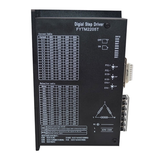
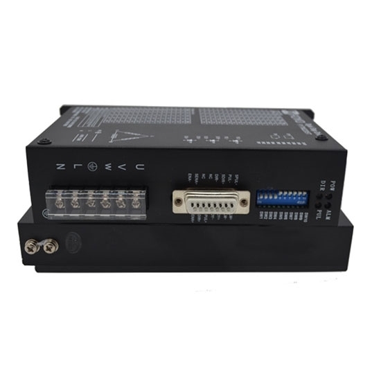
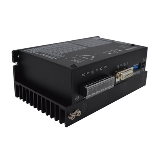
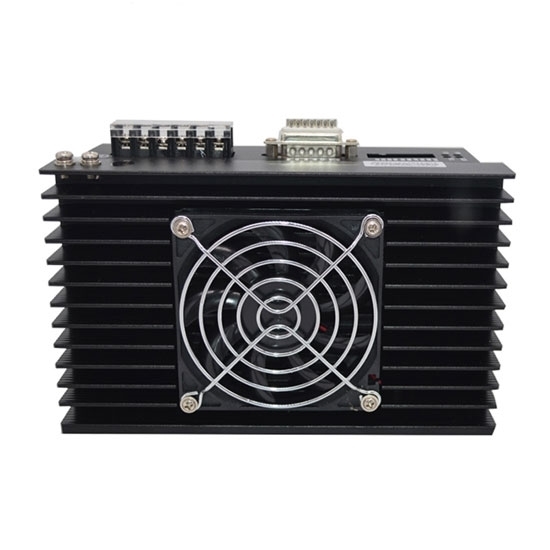
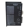
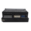
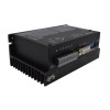
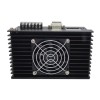
- Stock: In Stock
- Model: RDDLZ-STEP-M2205T
- Weight: 1.00
- SKU: RDDLZ-STEP-M2205T
Available Options
RDDLZ digital stepper motor driver with adjustable voltage and current, is an ideal choice for three phase Nema 34 bipolar stepper motor solution. This stepper motor controller can realize precise position control even without a feedback system.
Features
- Digital stepper motor driver is high performance, low price, low noise and good stability.
- Adopt unique control circuit to increase high-speed response and smoothness.
- Continuously adjustable drive current from 2.2A ~ 4.8A.
- When the pulse stops exceeds 100ms, the coil current is automatically halved.
- Average current control, two-phase sinusoidal current drive output.
- Suitable for3 phase Nema 34, hybrid bipolar stepper motors.
Specification
| Model | RDDLZ-FYTM2205T | |
| Matched Motor | Nema 34 3 Phase Stepper Motor | |
| Voltage | AC 90V ~ 230V | |
| Drive Current | 2.2A ~ 4.8A 16 Channels | |
| Microstepping Setting | 60000 steps/rev 16 Channels | |
| Hightest Pulse Frequency | 200Kpps | |
| Certification | CE, FCC, RoHS | |
| Dimensions | 178 x 108 x 67mm | |
| Weight | 1kg | |
| Function Description | ||
| Functions | Operation Instructions | |
| PUL+ | Positive End of Control Pulse Signal | Connect to +5V power supply, +5V ~ +24V can be driven, higher than +5V need to connect current limiting resistor. |
| PUL- | SW9=OFF, PUL is the pulse control signal | The falling edge is valid, and the motor takes one step whenever the pulse changes from high to low. Input resistance 220Ω. Requirements: low level 0 to 0.5V, high level 4 to 5V, pulse charge >2.5us. (This interface is shared with 24V negative pulse.) |
| SW9=ON, PUL is a positive pulse signal | ||
| DIR+ | Positive End of Directional Signal | Connect to +5V power supply, +5V ~ +24V can be driven, higher than +5V need to connect current limiting resistor. |
| DIR- | SW9=OFF, DIR is the direction control signal | Used to change the direction of the motor. Input resistance 220Ω. Requirements: low level 0 to 0.5V, high level 4 to 5V, pulse charge >2.5us. (This interface is shared with 24V negative pulse.) |
| SW9=ON, DIR is the reverse pulse signal | ||
| ENA+ | Positive End of Enabling Signal | Connect to +5V power supply, +5V ~ +24V can be driven, higher than +5V need to connect current limiting resistor. |
| ENA- | Negative End of Enabling Signal | When it is valid (low level), the motor coil current is turned off, the driver stops working, and the motor is in a free state. (This interface is shared with 24V negative pulse.) |
| ALM+ | Positive End of Alarm Signal Output | When over-current, over-voltage, under-voltage or over-tolerance alarms, the alarm signal is valid (the output photocoupler is turned on). ALM+ is connected to the pull-up power to use the positive pole of the output power supply, and ALM- is connected to the negative pole of the output power supply. Maximum drive current 50mA. |
| ALM- | Negative End of Alarm Signal Output | |
| RDY+ | Positve End of Ready to Signal output | The driver is in a normal state and is active when the controller signal is ready to accept (low level). |
| RDY- | Negative End of Ready to Signal output | |
| 24PUL+ | Positive End of Signal Input | +24V can be driven. (Its negative pulse interface is shared with 5V negative pulse interface.) |
| 24DIR+ | Positive End of Signal Input | +24V can be driven. (Its negative pulse interface is shared with 5V negative pulse interface.) |
| 24ENA+ | Positive End of Signal Input | +24V can be driven. (Its negative pulse interface is shared with 5V negative pulse interface.) |
Operating Current Setting
| Peak Current | SW1 | SW2 | SW3 | SW4 |
| 2.2A | off | off | off | off |
| 2.4A | off | off | off | on |
| 2.6A | off | off | on | off |
| 2.8A | off | off | on | on |
| 3.0A | off | on | off | off |
| 3.2A | off | on | off | on |
| 3.4A | off | on | on | off |
| 3.6A | off | on | on | on |
| 3.8A | on | on | off | off |
| 4.0A | on | on | off | on |
| 4.2A | on | off | on | off |
| 4.4A | on | off | on | on |
| 4.6A | on | on | off | off |
| 4.8A | on | on | off | on |
Microstep Segmentation Setting
| Pulse/Revo | SW5 | SW6 | SW7 | SW8 |
| 400 | on | on | on | on |
| 500 | on | on | on | off |
| 600 | on | on | off | on |
| 800 | on | on | off | off |
| 1000 | on | off | on | on |
| 1200 | on | off | on | off |
| 2000 | on | off | off | on |
| 3000 | on | off | off | off |
| 4000 | off | on | on | on |
| 5000 | off | on | on | off |
| 6000 | off | on | off | on |
| 10000 | off | on | off | off |
| 12000 | off | off | on | on |
| 20000 | off | off | on | off |
| 30000 | off | off | off | on |
| 60000 | off | off | off | off |
Dimensions (Unit: mm)
Wiring Diagram
Details
Tips: What is the advantage of stepper motor driver
The main advantage of stepper motor driver after subdivision is to completely eliminate the low frequency oscillation of the motor. Low frequency oscillation is an inherent characteristic of stepper motors, and subdivision is the only way to eliminate it. If your hybrid bipolar stepper motor sometimes needs to work in the resonance area, choosing a subdivision driver is the only choice. Improved the output torque of the motor. Especially for three-phase reactive motors, the torque ratio is increased by about 30-40% without subdivision, and the resolution of the motor is improved.
