

- Stock: In Stock
- Model: RDDLZ-STEP-D2030
- Weight: 1.00
- SKU: RDDLZ-STEP-D2030
Available Options
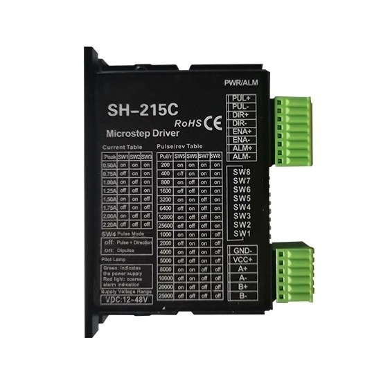
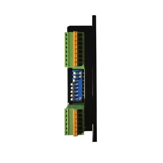
2-phase bipolar microstep motor driver, DC 20-30V, 0.31-1.68A for Nema 11, 14, 17 2 phase stepper motor, manufacturer direct sale.
Features:
- Input voltage 20-36 VC, typical value is 24V, chopping frequency is greater than 35KHz.
- Input signal is compatible with TTL, can drive two or four phase hybrid stepping motor.
- Bipolar constant current chopper, photoelectric isolation signal input, when the pulse signal to stop delay 1 s, motor current automatically by half, can reduce fever.
- Fine fraction optional: 2, 4, 8, 16, 32, 64, drive current can be set by the switch. The largest drive current of 1.68 A/phase.
- CP side for the pulse signal, falling edge effectively, greater than 5 μs falling edge pulse time, the signal logic input current of 10 mA-25 mA. DIR end as the direction of control signal, review dictates the motor running direction.
- ENA terminal for the drive enable, high or floating motor can run. Low-level driver output current, the motor is in a free state.
Specifications
| Basics Information | |||
| Model | RDDLZSH215B | ||
| Phase | 2 | ||
| Weight | 0.25 kg | ||
| Supply Power | DC 20-30V | ||
| Chopping Frequency | > 35KHz | ||
| Output Current | 0.31-1.68 A | ||
| Environment | |||
| Operation Environment | Temperature | -5℃~+40℃ | |
| Humidity | <80% RH | ||
| Vibration | 5.9m/s2 (Max.) | ||
| Storage Environment | Temperature | -40℃~+55℃ | |
| Humidity | <93% RH | ||
| Function Description | |||
| Functions | Operation Instructions | ||
| Signal Interface | PUL | PUL+ is the positive end of the control pulse signal PUL- is the negative end of the control pulse signal | |
| DIR | DIR+ is the positive end of directional signal DIR- is the negative end of directional signal | ||
| ENA | ENA+ is the positive end of enabling signal ENA+ is the negative end of enabling signal | ||
| Motor Interface | A | A+ is connected with the positive end of the A phase winding of the stepping motor A- is connected with the negative end of the A phase winding of the stepping motor | |
| B | B+ is connected with the positive end of the B phase winding of the stepping motor B- is connected with the negative end of the B phase winding of the stepping motor | ||
| When the A and B two phase windings are switched, the motor direction is reversed | |||
| Indicator Light | 1. The green light is the power indicating lamp. When the drive is powered on, the green light is always on. 2. The red light is the fault indicating lamp. When the overvoltage and overcurrent faults occur, the trouble lamp is always on. | ||
| Note: The default input signal is 5V pulse signal. When 24V input signal is required, please in series with1.8-2kΩ resistance. | |||
Switch of Options
Wiring Diagram
Installation Size (Unit: mm)
Details
Tips: Stepper motor needs stepper driver to drive
The operation of a stepper motor needs to be driven by a pulse-distributing power-type electronic device, i.e. a stepper motor driver. It receives pulse signals from a control system and distributes the pulses in sequence according to structural characteristics of the stepper motor to realize control of angular displacement, rotation speed, rotation direction, brake load state and free state. Each time the control system sends a pulse signal, the driver can drive the stepper motor to rotate by a step angle. The rotate speed of a stepper motor is proportional to the frequency of pulse signals. The amount of angular displacement is related to the number of pulses. When the stepper motor stops rotating, two states below can be generated: brake load leading to maximum or partial holding torque (generally called brake hold, without electromagnetic braking or mechanical braking) and the rotor in a free state (driven by external thrust force to easily rotate).
The stepper motor driver must match the model of the stepper motor. Otherwise, both of them may be damaged.
