Your Cart
We use cookies 🍪
We use cookies and other similar technologies to improve your browsing experience and the functionality of our site. Learn more in our Privacy Policy.
Free shipping all orders over on $200
30 days easy and hassle-free returns
24/48h Customer support available

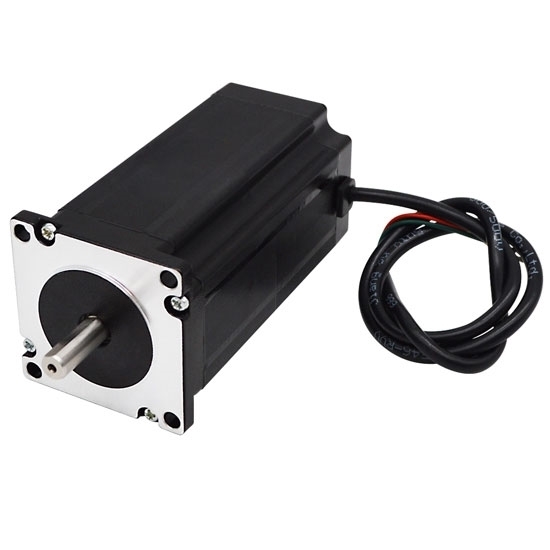
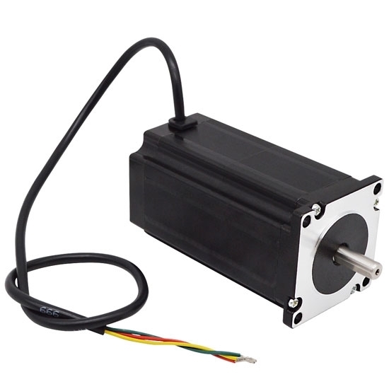
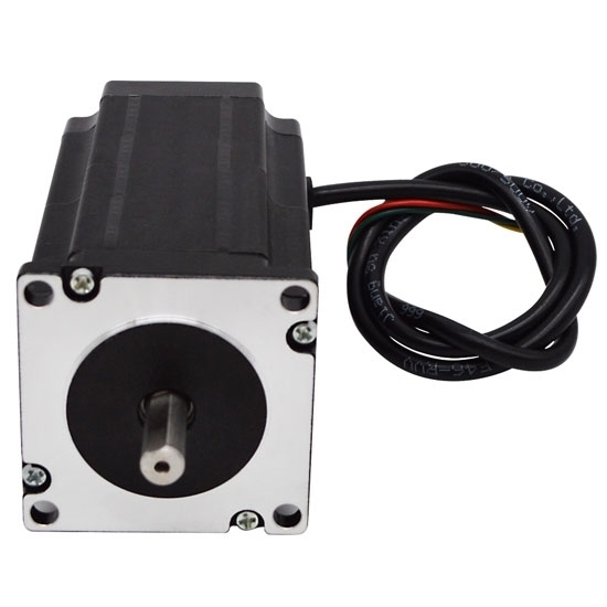
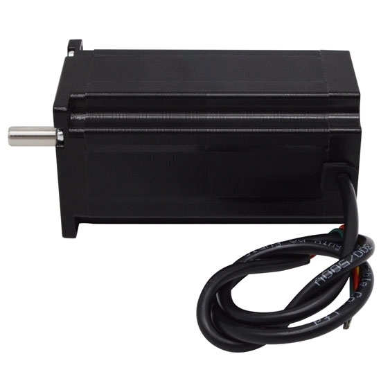
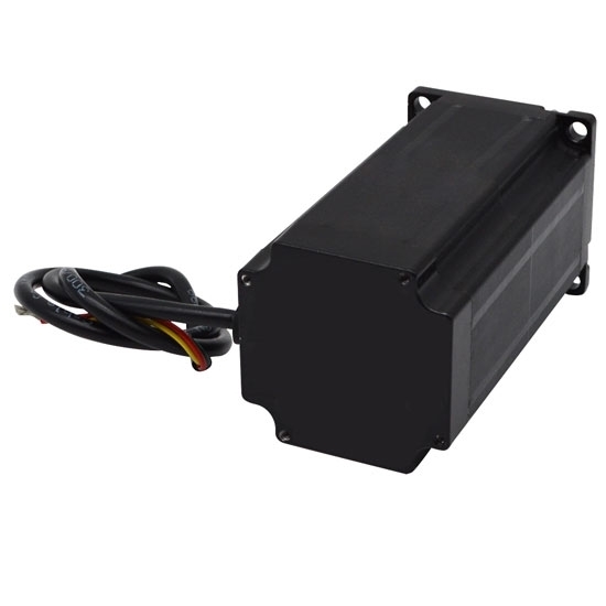
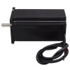
Nema 23 Stepper Motor, 3 Phase, 5.3A, 0.9N·m

Nema 23 Stepper Motor, 3 Phase, 5.3A, 0.9N·m
from
$85.95
Ex Tax: $85.95
  • Stock: In Stock
  • Model: RDDLZ-STEP-23M530
  • Weight: 1.00
  • SKU: RDDLZ-STEP-23M530

Available Options

Create unlimited custom product blocks and display them in accordions or tabs or open blocks. Each block can be assigned to all products at once or specific products according to advanced criteria.

Industral 3 phase permanent magnet stepper motor with 3 lead wires is convenient to adjust the speed, long service life and low maintenance cost.

Physical Specification

  • Model Number: RDDLZ-FY56TM530A
  • Flanged Size: 57 x 57mm (Nema 23)
  • Motor Length: 54mm
  • Shaft Diameter: 8mm
  • Number of Leads: 3 wire
  • Weight: 0.7kg

Electrical Specification

  • Motor Type: Bipolar Stepper
  • Step Angle: 1.8°
  • Rated Current: 5.3A
  • Holding Torque: 0.9 N·m (90 N·cm, 127.5 Oz.in)
  • Phase Resistance: 0.35Ω
  • Phase Inductance: 1.1mH
  • Rotor Inertia: 300g·cm2

Dimensions (Unit: mm)

L=54mm

Wiring Diagram

Speed-Torque Curve Diagram

Details

Tips: Difference between unipolar stepper motor and bipolar stepper motor

The bipolar stepper motor uses eight transistors to drive two sets of phases. The number of transistors in a bipolar motor drive circuit is twice that of a unipolar drive circuit. The four lower-end transistors are usually directly driven by a microcontroller, and the upper-end transistors require a higher-cost upper-end drive circuit.

The main difference between a high torque unipolar stepper motor and a bipolar stepper motor is the connection. The motor structure of the unipolar drive circuit contains two sets of coils with middle taps, and the whole motor has a total of six wires connected to the outside world. The bipolar drive circuit can drive a four-wire or six-wire motor at the same time. Although a four-wire motor can only use a bipolar drive circuit, it can greatly reduce the cost of mass production applications.

In addition, they are also different in voltage. The transistors of the bipolar drive circuit only need to bear the motor voltage, while the unipolar drive circuit needs a clamp circuit to drive.

Write a review

Note: HTML is not translated!
Rating
Bad Good

Builder in Product TAB

NEW! Since Journal 3.2, the much improved T.A.B (Tabs Accordion Blocks) system supports the page builder inside the tab content. Unlimited Blocks, Tabs or Accordions with any HTML content or the builder interface (supporting custom rows/columns/modules) can be assigned to any individual product or to certain groups of products, like entire categories, brands, products with specific options, attributes, price range, etc. You can indicate any criteria via the advanced product assignment mechanism and only those products matching your criteria will display the modules. Also, any module can be selectively activated per device (desktop/tablet/phone), customer login status and other criteria. Imagine the possibilities.