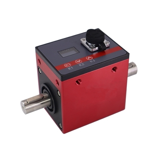
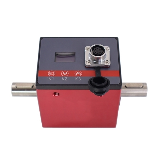
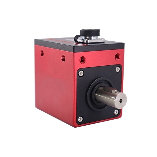
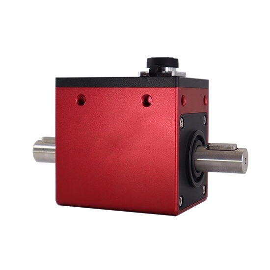
- Stock: In Stock
- Model: RDDLZ-TQS-D03
- Weight: 1.00
- SKU: RDDLZ-TQS-D03
Available Options
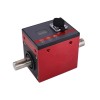
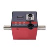
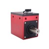
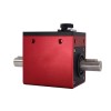
Rotary torque sensors have capacity range from 0.1 Nm, 0.3 Nm, 0.5 Nm, 1 Nm, 2 Nm, 5 Nm, 10 Nm, 20 Nm, 100 Nm, 300 Nm, 1000 Nm, 5000 Nm to ±10000 Nm. Torque sensor capacity can be customized according to customer requirements. RDDLZ torque sensor can directly output standard signal (±5V/0-10V/4-20mA/RS485) to PLC, DCS and other automation control systems.
Specification
| Model | RDDLZ-TQS-DYN-200 | |||||
| Capacity Range * | 0.1Nm~5 Nm | 10Nm~100 Nm | 200Nm~300 Nm | 500Nm~800 Nm | 1000Nm~5000 Nm | 10000 Nm |
| Net Weight | 1.3kg | 1.4kg | 2kg | 3.5kg | 8kg | 16kg |
| Shipping Weight | 2.5kg | 2.5kg | 3kg | 4.5kg | 10kg | 18kg |
| Display | LCD display (show torque/speed/power value) | |||||
| Non-linearity | 0.1%FS (Accuracy 0.001 * Capacity=Lowest Nm) | |||||
| Hysteresis | 0.03%FS | |||||
| Repeatability | 0.03%FS | |||||
| Temperature Drift on Zero | <0.01%FS/°C | |||||
| Temperature Effect on Output | <0.01%FS/°C | |||||
| Power Supply | DC 24V | |||||
| Consumption Current | <150mA | |||||
| Load Resistance | ≥2kΩ | |||||
| Output Torque * | ±5V, 0-10V, 4-20mA, RS485, RS485 & ±5V, RS485 & 0-10V, RS485 & 4-20mA | |||||
| Software Option* | Including software and USB to RS485 cable, you can install software on your computer (Win 8/ Win 10 system) to monitor torque data and graphs. | |||||
| Output Speed | 60 pulse per revolution (OC output is standard configuration, and 5V TTL output is optional) | |||||
| Response Frequency | 1kHz | |||||
| Acquisition Speed | 550/1200 times/s | |||||
| Signal Delay | 0.6ms | |||||
| Ultimate Overload | 200%FS | |||||
| Rated Speed | Range≤500Nm: 8000rpm; Range>500Nm: 6000rpm | |||||
| Maximum Speed | Range≤500Nm: 10000rpm; Range>500Nm: 8000rpm | |||||
| Protection Grade | IP43 | |||||
| Maximum Deformation | 0.149°/1Nm at 2.60*10rad (The maximum deformation angle generated by 1Nm at 2.6*10rad rotation arc is 0.149°) | |||||
| Inertia Moment | 0.38x10⁻⁴ - 0.35x10⁻³ kg·cm2 | |||||
| Natural Vibration Frequency | 19.4kHz | |||||
| Torsion Constant | 0.833×10Nm - 3602.7×10Nm/rad | |||||
| Elastic Element Material | 17-4 stainless steel | |||||
| Operating Temperature | -10°C~+70°C (14~158℉) | |||||
| Humidity | 0~85%RH | |||||
| Electrical Connection | 7 pin waterproof circular connector | |||||
| Cable Length | 3m (Φ5mm) | |||||
Details
Connection
Dimension (unit: mm)
1. Dimension for capacity 0.1~5 Nm (Basic Thread: 53*53, 4-M8-1.25 depth 10)
2. Dimension for capacity 10~100 Nm (Basic Thread: 53*53, 4-M8-1.25 depth 10)
3. Dimension for capacity 200~300 Nm (Basic Thread: 53*53, 4-M8-1.25 depth 10)
4. Dimension for capacity 500~800 Nm (Basic Thread: 75*60, 4-M8-1.25 depth 12)
5. Dimension for capacity 1000~5000 Nm (Basic Thread: 75*60, 4-M8-1.25 depth 10)
6. Dimension for capacity 10000~20000 Nm (Basic Thread: 120*80, 4-M12-1.75 depth 25)
Installation
Installation Precautions
Keyway Installation: If a torque transducer or keyway connection falls out, it may cause damage or injury, so take measures such as installing a pin to prevent it from falling out. Make sure that the keyway is undamaged and that the torque transducer is securely mounted.
Mounting Method: The digital rotary torque sensor can be used in horizontal or vertical orientation. There is no restriction on the direction of the cable. When installing the torque transducer to other devices, hold the frame of the sensor and secure the frame with a hard bubble amphoteric acid to prevent the frame from rotating.
Tips: How does a digital rotary torque sensor work?
Digital rotary torque sensors measure torque through techniques such as strain gauge or electromagnetic induction and convert it into an electrical signal. A signal processing module inside the sensor converts the analog signal into a digital signal to ensure high accuracy and low interference. The data can be transmitted to a display device or control system through wired or wireless means to realize real-time monitoring and feedback.
When mounting, ensure that the sensor axis is coaxial with the measurement system to avoid additional mechanical stress affecting measurement accuracy. When fixing the sensor, use a suitable coupling and ensure that there is no axial or radial offset. For calibration, calibrate the torque sensor using standard torque equipment or known loads, and adjust the zero point and scale factor according to the software or hardware provided by the manufacturer to ensure measurement accuracy.
