- Stock: In Stock
- Model: RDDLZ-LCTR-NTB3K
- Weight: 1.00
- SKU: RDDLZ-LCTR-NTB3K
Available Options
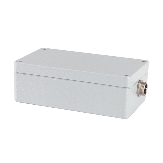
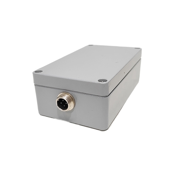
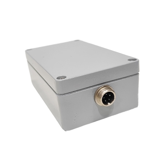
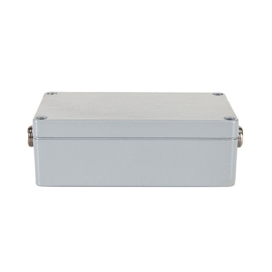
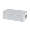
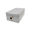
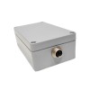
The low cost RDDLZ-NTB3K is in hot sale, as a high precision single-channel load cell weight transmitter, the signal output can be optional 0-5V/0-10V/4-20mA/0~±5V/0~±10V, ensuring the accurate data transmission. With IP65 protection, power supply voltage of 10-36VDC, compact and lightweight body, easy to be integrated into automation systems.
Specification
| Model | RDDLZ-NTB3K |
| Rated Input | ±20mV |
| Single Output (optional) | V1: 0~5V |
| V2: 0~10V | |
| V3: 0~±5V | |
| V4: 0~±10V | |
| A1: 4~20mA | |
| Simultaneous output V1+A1 | |
| Channel | Single channel |
| Precision | ≤±0.1%F-S |
| Supply Voltage | 10 (12) ~36V DC |
| Working Temperature | -20°C~70°C |
| Protection Level | IP65 |
| Size | 110*64*37mm |
| Net Weight | ≤0.5kg |
Feature
- Precision die-cast aluminum transmitter housing with plastic sprayed surface, suitable for high precision level and harsh environment.
- Adopting anti-interference power supply design technology, the load cell weight transmitter has good electromagnetic compatibility (EMs).
- The wiring adopts terminal and aviation plug, and there are mounting holes in the shell. In addition to the characteristics of a normal load cell transmitter, it also reduces the harmonic interference generated by frequency converters and so on.
- The analog output of this load cell transmitter can be 0-5V, 0-10V, 0-±5V, 0-±10V, 4-20mA (optional).
Dimension (unit: mm)
Wiring Instruction
As the figure above shows: There are two wiring terminals J1 and J2 in the whole board diagram.
LEFT J1 is the terminal connecting the sensor:
| PB | Connect the sensor shielded wire | blue wire |
| E+ | Connect the positive wire of the sensor excitation power supply | red wire |
| E- | Connect the negative wire of the sensor excitation power supply | black wire |
| S+ | Connect the positive wire of the sensor signal output | green wire |
| S- | Connect the negative wire of the sensor signal output | white wire |
RlGHT J2 is the terminal connecting the transmitter to the power supply and output:
| IOUT | Connect the transmitter current output positive wire | white wire |
| VOUT | Connect the positive voltage output wire of the transmitter | white wire |
| (current and voltage are only output at the same time) | ||
| GND | Connect the negative wire of the transmitter power supply | blue wire |
| 24V | Connect the positive wire of the transmitter power supply | red wire |
There are 2 adjustable resistors in the whole board diagram: RP2 is gain adjustment, RP1 is voltage zero adjustment.
Tips: What are the common faults and troubleshooting methods of load cell weight transmitter?
Common faults include no signal output, unstable output signal or large error.
- No Signal Output: Check whether the power supply is normal, whether the wiring is correct, and whether the load cell transmitter is damaged.
- Unstable Signal: Check whether there is electromagnetic interference, whether the load cell sensor is subject to external vibration, and whether it is well grounded.
- Excessive Error: Is the calibration correct, is the sensor overloaded or damaged. Regular maintenance and calibration can ensure measurement accuracy and equipment stability.
