

- Stock: In Stock
- Model: RDDLZ-CPS-HCM375B
- Weight: 1.00
- SKU: RDDLZ-CPS-HCM375B
Available Options
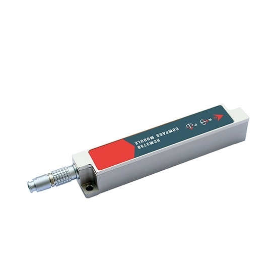
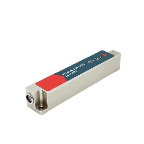
The electronic compass integrates a three-axis magnetic field sensor and a three-axis acceleration sensor. It uses an industrial microcontroller with high reliability and strong anti-interference ability to calculate heading data in real time, and uses a three-axis accelerometer to compensate for heading angles over a large range.
Feature
- Electrical compass sensor adopts hard and soft iron calibration algorithms, combined with high-precision accelerometer for tilt compensation to ensure high accuracy of direction measurement.
- It has high resolution and strong noise resistance, and stable temperature offset, ensuring data reliability under various environmental conditions.
- The electronic compass has an IP67 waterproof rating, making it perform well in harsh environments such as drilling measurements.
- 3D electronic compass sensor is compact in design, low in power consumption, and provides high performance and stability, suitable for various application scenarios.
Specification
| Model | RDDLZ-HCM375B | |
| Compass heading parameters | Heading accuracy (RMS) | 0.5° tilt <10° |
| 2.0° tilt <60° | ||
| 3.0° tilt <80° | ||
| Resolution | 0.1° | |
| Compass inclination parameters | Pitch accuracy (RMS) | 0.1° <15° (measuring range) |
| 0.1° <30° (measuring range) | ||
| 0.1° <60° (measuring range) | ||
| 0.2° <85° (measuring range) | ||
| Pitch tilt range | ±85° | |
| Roll accuracy | 0.1° <15° (measuring range) | |
| 0.1° <30° (measuring range) | ||
| 0.1° <60° (measuring range) | ||
| 0.3° <180° (measuring range) | ||
| Roll tilt range | ±180° | |
| Resolution | 0.1° | |
| Calibration | Hard iron calibration | ✔ |
| Soft iron dalibration | ✔ | |
| Magnetic field interference calibration method | Plane rotates one circle (two-dimensional calibration) | |
| Physical properties | Size | L111.5×W19.5×H19.5mm |
| Connectors | 5 PIN aviation socket | |
| Interface Characteristics | Startup delay | <50ms |
| Output signal | RS232/RS485/TTL (optional) | |
| Output rate | 20Hz/s | |
| Power supply | Supply voltage | (Default) DC +5V |
| Current (MAX) | 30mA | |
| Ideal mode | 26mA | |
| Sleep mode | TBD | |
| Environment | Operating range | -40℃~+85℃ |
| Storage temperature | -40℃~+85℃ | |
| Vibration resistance | 100g | |
| Protection level | IP67 | |
| Electromagnetic compatibility | According to EN61000 and GBT17626 | |
| MTBF | ≥40000 hours/time | |
| Insulation resistance | ≥100 megohm | |
| Vibration resistance | 10grms, 10~1000Hz | |
| Weight | ≤85g | |
Dimension (mm)
Signal Definition
Applications
Installation direction diagram
Tips: Installation instructions for high-accuracy electronic compass sensor
Since high-precision electronic compass relies on geomagnetic principles for azimuth measurement, it is essential to install it in an environment with minimal magnetic interference. Ensure that the sensor is placed as far away as possible from iron objects, magnets, engines, and other magnetic materials. Even in the presence of these magnetic sources, maintain a minimum distance of at least 30cm from the compass, as the interference distance may vary depending on the strength of the magnetic field. To achieve optimal measurement performance, use anti-interference screws during installation.
