

- Stock: In Stock
- Model: RDDLZ-STEP-D80220
- Weight: 1.00
- SKU: RDDLZ-STEP-D80220
Available Options
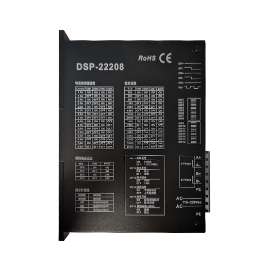
2-phase digital stepper driver, 80-220V AC power supply for 2 phase Nema 34, 42 stepper motor, manufacturer direct sale.
Features:
- 32-bit DSP digital control mode.
- Low vibration, low noise, low power consumption.
- Flexible subdivision runs more smoothly.
- Automatic memory power phase.
- Optically isolated input signal.
- Space vector bipolar constant current drive.
- Maximum output current 7.5A / phase.
- Provide energy-saving automatic half-current lock function.
- Maximum 25600 steps / turn of the 16 subdivision mode optional.
Specifications
| Basics Information | |||
| Model | RDDLZDSP22208 | ||
| Size | 135 x 77 x 46 mm | ||
| Phase | 2 | ||
| Weight | 1.5 kg | ||
| Supply Power | 80-220V AC | ||
| Capacity | 0.8 kVA | ||
| Output Current | Peak 7.5A/Phase (Max.) | ||
| Driver Method | Space vector bipolar constant current drive | ||
| Isolation Resistance | >500 MΩ | ||
| Dielectric Strength | 1kV, 1Min | ||
| Cooling Method | Natural Convection | ||
| Environment | |||
| Operation Environment | Temperature | -5℃~+40℃ | |
| Humidity | <80% RH | ||
| Vibration | 5.9m/s2 (Max.) | ||
| Storage Environment | Temperature | -40℃~+55℃ | |
| Humidity | <93% RH | ||
| Function Description | |||
| Functions | Operation Instructions | ||
| Signal Interface | PUL | PUL+ is the positive end of the control pulse signal PUL- is the negative end of the control pulse signal | |
| DIR | DIR+ is the positive end of directional signal DIR- is the negative end of directional signal | ||
| ENA | ENA+ is the positive end of enabling signal ENA+ is the negative end of enabling signal | ||
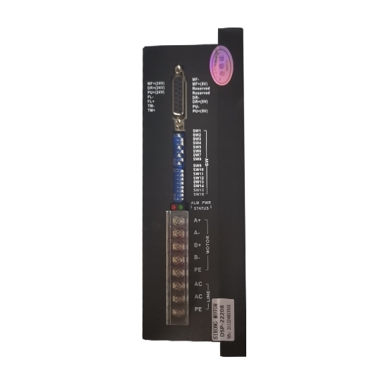
| Motor Interface | A | A+ is connected with the positive end of the A phase winding of the stepping motor A- is connected with the negative end of the A phase winding of the stepping motor | |
| B | B+ is connected with the positive end of the B phase winding of the stepping motor B- is connected with the negative end of the B phase winding of the stepping motor | ||
| When the A and B two phase windings are switched, the motor direction is reversed | |||
| Indicator Light | 1. The green light is the power indicating lamp. When the drive is powered on, the green light is always on. 2. The red light is the fault indicating lamp. When the overvoltage and overcurrent faults occur, the trouble lamp is always on. | ||
| Note: The default input signal is 5V pulse signal. When 24V input signal is required, please in series with1.8-2kΩ resistance. | |||
Driver Wiring Diagram
Installation Size (Unit: mm)
Details
Tips: Current comparison chopper drive method for stepper motor
Current comparison chopper drive is to convert the stepper motor’s winding current into a certain percentage of voltage, which is compared with the preset value output by a D / A converter, the result of which comparison is used to control the switch of power tube for the purpose of control of the winding phase current.
Advantages: To make motion control simulate characteristics of sine waves, greatly improving performance, relatively small speed and noises, higher subdivision able to be used, current popular control method.
Disadvantages: The circuit is more complex. It is difficult to control circuit interference which should be consistent with theoretical requirements. Vibration is easy to occur. In the control of formation of crests and troughs of sine waves, high-frequency interference is easily led to, which further leads to heating of drive elements or aging because of excessively high frequency. That is also the main reason why red light protection tends to occur when many drives are used for more than one year.
