

- Stock: In Stock
- Model: RDDLZ-CPS-DCM302B
- Weight: 1.00
- SKU: RDDLZ-CPS-DCM302B
Available Options
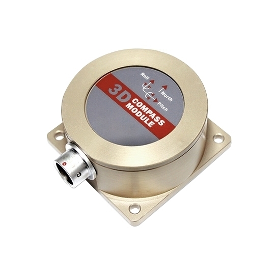
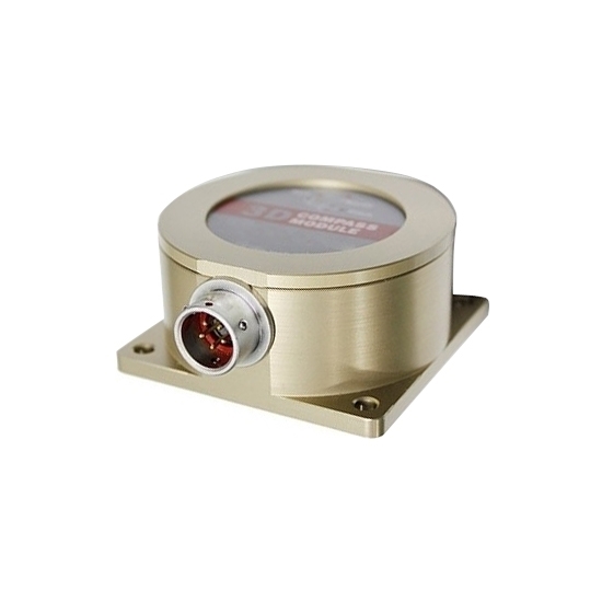
High-precision 3D electronic compass sensor that uses a two-dimensional plane calibration algorithm. Calibration does not require three-dimensional attitude tilting, and the calibration process is completed by simply rotating the plane in place. The hard magnetic and soft magnetic calibration algorithms using imported technology enable the compass to achieve ideal measurement results through three-dimensional calibration methods even in an environment with magnetic field interference.
The electronic compass integrates a three-axis magnetic induction technology sensor, calculates the heading in real time through the central processor, and uses a three-axis accelerometer to compensate for the tilt angle in a wide range, ensuring that the compass can provide high-precision heading data even when the tilt angle is as high as ±85°.
Specification
| Model | RDDLZ-DCM302B | |
| Compass heading parameters | Heading accuracy (RMS) | 0.5° tilt <10° |
| 1.0° tilt <30° | ||
| 2.0° tilt <40° | ||
| 2.5° tilt <70° | ||
| Resolution | 0.1° | |
| Compass inclination parameters | Pitch accuracy (RMS) | 0.1° <15° (measuring range) |
| 0.2° <30° (measuring range) | ||
| 0.3° <60° (measuring range) | ||
| 0.3° <85° (measuring range) | ||
| Pitch tilt range | ±85° | |
| Roll accuracy | 0.1° <15° (measuring range) | |
| 0.2° <30° (measuring range) | ||
| 0.3° <60° (measuring range) | ||
| 0.3° <85° (measuring range) | ||
| Roll tilt range | ±85° | |
| Resolution | 0.1° | |
| Tilt compensation angle range | <40° | |
| Calibration | Hard iron calibration | ✔ |
| Soft iron calibration | ✔ | |
| Magnetic field interference calibration method | Plane rotates one circle (two-dimensional calibration) | |
| Physical properties | Size | L60×W59×H33mm |
| Connectors | 5 PIN aviation socket | |
| Interface Characteristics | Startup delay | <50ms |
| Output signal | RS232/RS485/TTL (optional) | |
| Output rate | 20Hz/s | |
| Output format | Binary high performance protocol | |
| Power supply | Supply voltage | (Default) DC +5V |
| (Customized) DC 9~36V | ||
| Current (MAX) | 45mA | |
| Ideal mode | 30mA | |
| Sleep mode | TBD | |
| Environment | Operating range | -40℃~+85℃ |
| Storage temperature | -40℃~+100℃ | |
| Vibration resistance | 2500g | |
| Protection level | IP67 | |
| Electromagnetic compatibility | According to EN61000 and GBT17626 | |
| MTBF | ≥40000 hours/time | |
| Insulation resistance | ≥100 megohm | |
| Vibration resistance | 10grms, 10~1000Hz | |
| Weight | ≤150g | |
Dimension (mm)
Wiring
Applications
Installation direction diagram
Tips: Installation instructions for the 3D electronic compass sensor
Since the DCM302B 3D electronic compass sensor uses the geomagnetic principle to measure azimuth, it is important to choose an installation environment with minimal magnetic interference. Please try to keep the electronic compass sensor away from iron, magnets, engines and other magnetic objects, at least 40 cm away (the specific interference distance will vary depending on the magnetic field strength). It is recommended to use M4 anti-interference screws during installation to ensure the best measurement effect. Although the DCM302B can compensate for moderate deviations in a stable magnetic environment, it cannot compensate for changing magnetic interference. Pay special attention to the magnetic field changes generated by DC wires, because changes in DC current will affect the magnetic field strength, and batteries may also become interference sources. Therefore, each installation environment requires the user to evaluate its feasibility.
The heading accuracy of the 3D electronic compass sensor can reach 0.5°~0.8°, and this accuracy has been strictly verified. The recommended test method is to install the DCM302B on a vertical aluminum (or other non-magnetic material) pole, measure the heading accuracy, and minimize external magnetic field interference. This method can reduce the compass turning radius and improve measurement accuracy. However, actual installation needs to be adjusted according to specific circumstances. For example, when installing on a vehicle, the electronic compass sensor should be mounted perpendicular to the direction of movement.
