

- Stock: In Stock
- Model: RDDLZ-RFFA-3DB10W
- Weight: 1.00
- SKU: RDDLZ-RFFA-3DB10W
Available Options
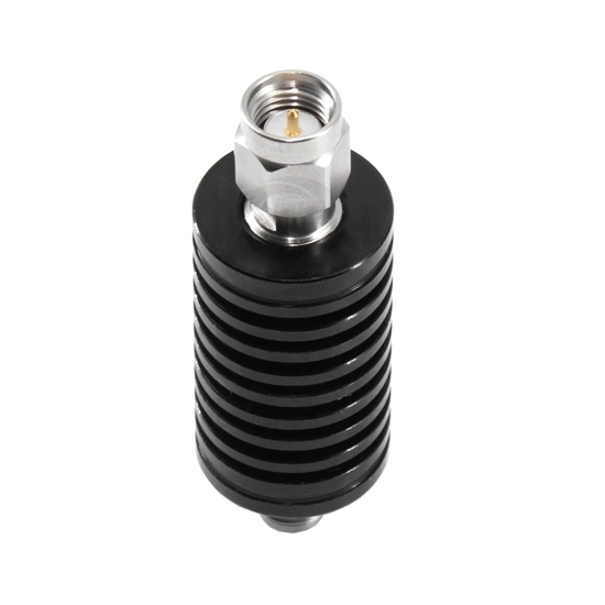
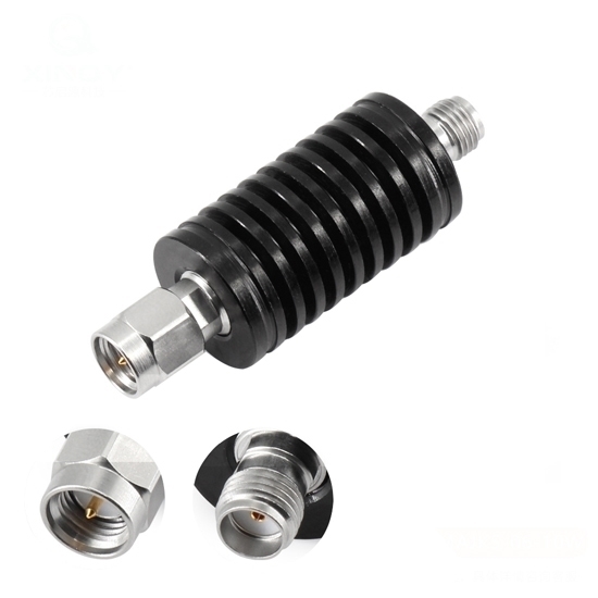
RF fixed coaxial attenuator utilizing SMA connector, seamlessly integrates in-line within radio frequency systems. Microstrip attenuators leverage printed circuit board technology to achieve precision in signal attenuation across specific frequency bands. This is particularly crucial in applications such as GPS, where maintaining accurate signal strength is paramount.
Specification
- Model: RDDLZ-SMAJKS-18-10W-3dB
- Frequency Range (Optional): DC~18GHz
- Standing Wave Ratio (VSWR): 1.35 (Max)
- Attenuation Value: 3dB
- Impedance: 50 Ohm
- Power: 10W
- Dielectric Withstand Voltage: 1000V
- Insulation Resistance: ≥5000MΩ
- A connector Type: SMA-Male
- B connector type: SMA-Female
- Working Temperature: -55℃~+100℃
- Inner Conductor Material: Beryllium Bronze with Gold Plating
- Outer Conductor Material: Stainless Steel Passivated
- Insulator: PTFE
- Service Life: ≥500
Dimension (Unit: mm)
Tips: What is a fixed RF attenuator's VSWR (Voltage Standing Wave Wave Ratio)?
A fixed RF attenuator's Voltage Standing Wave Ratio (VSWR) depends on its design and characteristics. Generally, a well-designed attenuator minimizes signal reflections and maintains a consistent impedance match to minimize VSWR. Ideally, a fixed attenuator should exhibit a VSWR close to 1:1, indicating minimal signal reflection and efficient power transfer. However, practical limitations may result in slightly higher VSWR values, often within the range of 1.1 to 1.5. Engineers consider factors such as impedance matching and the attenuator's construction to optimize VSWR. Regular calibration and testing are essential to ensure that the attenuator meets performance expectations, as VSWR directly influences signal integrity and power efficiency in RF systems.
