- Stock: In Stock
- Model: RDDLZ-SLPRV-DN40
- Weight: 1.00
- SKU: RDDLZ-SLPRV-DN40
Available Options
Note: This pressure relief valve cannot be used for drinking water.
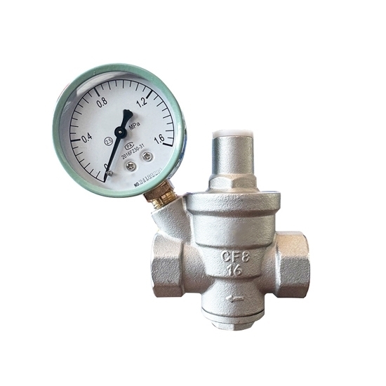
Buy a spring loaded pressure relief valve with 11/2" thread. The pressure reducing valve has the advantages of simple structure, small size, stable outlet pressure, and long service life.
Features
- The pressure relief valve accurately controls the dynamic and static pressure, and does not fluctuate due to changes in upstream pressure.
- Its dual piston has a large flow rate (about 3 times that of common similar valves) and low flow noise. This valve is made of stainless steel, which is high-strength and environmentally friendly.
- The internal structure of the spring loaded pressure relief valve is compact and reasonable, saving a lot of installation space.
- The installation environment requirements are simple, the pressure adjustment is wide, and the optimal water supply pressure can be adjusted on site without professional operation.
Specifications
- Model: RDDLZ-Y13X-16P
- Connection Method: Internal Thread
- Material: Stainless Steel 304
- Pressure Level: 1.6Mpa
- Size: 1-1/2 inch (DN40)
- Using Temperature: 0-80℃
- Applicable Media: Water, Oil, Normal Temperature Gas
- Pressure Specification: Sealing PN=1.76MPa; Strength PN=2.4MPa
- Total Valve Height: 175mm
- Total Valve Length: 100mm
- Application: Applicable to water supply and drainage pipeline systems in power, urban construction and other industries.
Installation Precautions
- For easy operation and maintenance, the pressure relief valve is generally installed upright on a horizontal pipe.
- During installation, care should be taken to ensure that the flow direction of the medium in the pipeline is consistent with the direction of the arrow shown on the valve.
- In order to prevent the valve from being blocked by debris, a filter should be installed at the front end of the pressure relief valve.
- In situations where the supply cannot be interrupted, a bypass valve should be provided or a dual-circuit method should be used, one for use and one for backup.
- When passing water for the first time, care should be taken to exhaust the air in the pipeline to avoid false pressure, to protect the pressure gauge and obtain the correct pressure.
Pressure Relief Valve Applications
Tips: Why does the pressure at the oil outlet of the pressure relief valve rise by itself?
In some decompression control loops, the outlet pressure of the decompression valve is used to control the control oil pressure of the electro-hydraulic directional valve or external control sequence valve. After working in the direction or direction, the flow rate at the oil outlet of the pressure reducing valve becomes zero, but the pressure still needs to maintain the original set pressure. In this case, since the valve outlet flow is zero, the flow through the decompression port is only the pilot flow. Since the pilot flow is very small, generally within 2L/min, the main valve decompression port is basically close to the fully closed position (the opening is very small), and the pilot flow flows out from the triangular groove or inclined cone surface. If the main valve core cooperates If it is too loose or worn too much, the leakage will increase. According to the flow continuity theorem, this part of leakage must also flow from the damping hole of the main valve core, that is, the flow flowing through the damping hole is composed of two parts: pilot flow and leakage, and the area of the damping hole and the oil pressure in the spring chamber of the main valve (the oil pressure in the spring chamber is determined by the pre-compression of the adjusted pressure regulating spring), in order to increase the flow through the damping hole, the oil pressure in the lower chamber of the main valve will inevitably increase. Therefore, when the outlet pressure of the pressure reducing valve is adjusted, if the outlet flow rate is zero, the outlet pressure will increase due to the loose fit of the main valve core or excessive wear.
